Polar Pattern Madness
What does that switch on the box really do?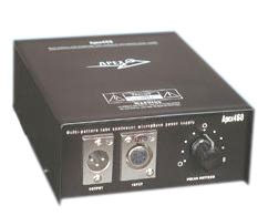
We were working on a upgrade recently and while doing our quality control tests I realized that we don't provide sweeps for all nine positions on a the standard multi-pattern microphones we upgrade. For reasons of simplicity I always just check the Cardiod position, the Omni Position and the Figure eight position.
But of course that begs the question, what the heck those "in between" postions do to the sound.
So for myself and everybody else who uses these things I thought I would publish the response changes that occurr with each switch position on our m251 upgrade to the APEX 460. Our standard 251 upgrade uses the CEK251 capsule, so as they say your mileage may vary, but this gives everyone some insight into how the response changes when you play with these different voltages on the capsule.
I was a little surprised to see how much the response varies and after seeing the results, I think that if you have a good room, meaning little reflections, you can probably cover a lot of ground with one of these 9 pattern mics. The range of sound goes from high end push to midrange push and quite bit in between.
How The Nine-Position Polar Pattern Works
I think it's good to start by talking about what happens when we spin that rotary control on the microphone power supply. The magic behind the pattern control is the interaction of the voltage on two diaphragms compared to "back-plate" which is in between. In the most simple terms, if the sound from both diaphragms is in phase we have an Omni microphone. If the diaphragms are out of phase we get a figure-eight pattern. The magic is in how we make that happen.
The front diaphragm of the microphone is connected to ground and so has zero volts on it. The centre element, the "back-plate"of the capsule, has a fixed (not adjustable) "polarization" voltage applied to it. The word "polarization" here is used in the electrical sense meaning a voltage that puts a charge on the element. That centre element voltage is typically around 60 volts.
The Audio signal in this multi-pattern circuit is taken from the back-plate through a DC blocking capacitor. In other words only changes in the voltage get through to the tube, not the polarization voltage. And because the back-plate is common to the front and back diaphragm it acts like a kind of mixer of both signals.
The back diaphragm has a variable voltage applied to it. This voltage is controlled by the nine position switch. The back diaphragm voltage goes from zero volts minimum and goes up to a maximum of double what is on the back-plate, in nine steps. In fact you could replace that 9 position switch with a high resistance poteniometer (variable resistor) and have infinite polar pattern control.
By adjusting the back voltage we change the signal output that is generated by the back capsule and the magic part... we can also adjust the electrical phase of the signal coming from the back diaphragm.
The Omni Position
With the centre element locked at 60 volts and the front connected to ground we get a signal from the front that we can call the reference. If we also ground the back diaphragm too, we have two identical microphones back to back, making the same signal level and in the same phase and so we get an Omni pattern microphone.
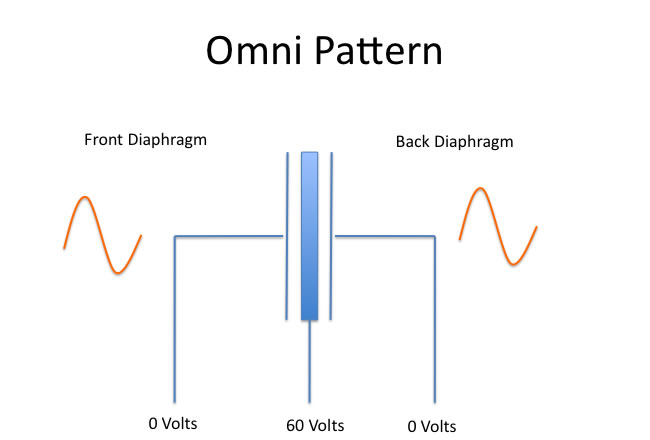
Audio output signal comes from the centre (back plate) connection
The Cardiod Positions
The images below show the middle position or normal Cardiod position. To achieve this polar pattern the voltage on the front of course is zero so we get an output signal because of the difference between the front diaphragm and the back plate voltages.
The back capsule diaphragm is set to the same voltage as the back plate. Since the output signal depends on the voltage difference between the two plates, there is NO electrical difference and so NO signal is generated. Voila! Cardiod pickup
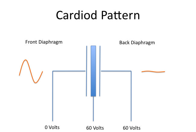
Figure 8
Now the figure eight pattern is the trickiest to understand. remembering that signals come from the difference between the back plates and diaphragm, we now set the back capsule to 120 volts. That means that there is a 60 volt difference between the back plate and the back diaphragm, but it's 60 volts more instead of sixty volts less.
What this does is reverses the phase of the electrical signal coming off the back diaphragm compared to the front diaphragm that is set to zero volts. This is because relative to the back plate, the polarity is reversed! The back is 60 volts positive compared to the back plate, whereas the front diaphragm is 60 volts negative compared to the back plate. Clever trick isn't it?
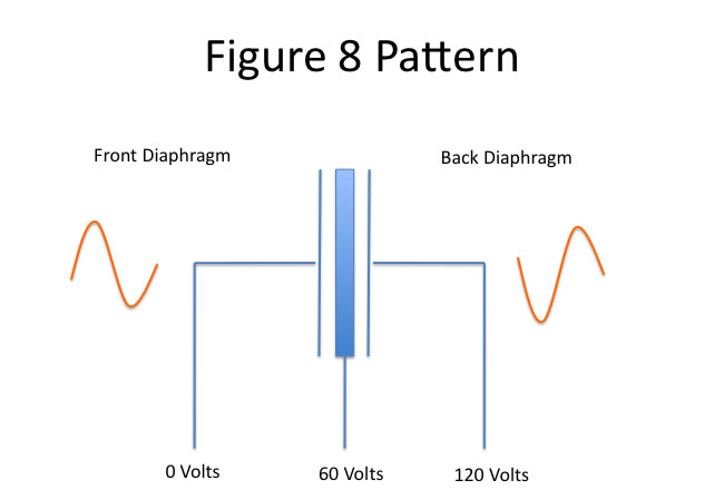
So when a sound hits both diagphrams equally, the front and back signals are out of phase and the back-plate puts out no signal, creating the Figure 8 null on the side of the microphone.
Polar Pattern Frequency Responses
Below we have recorded the frequency response of a FAR 251 upgrade in all nine polar patterns.
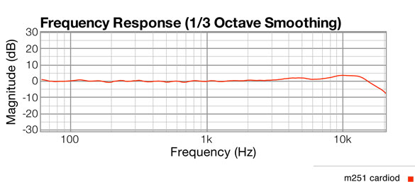
The Cardiods
The cardiod response has a 1 dB lift between 4Khz and 5Khz, with 3 to 4 dB lift centred at 11Khz. We sculpt this part of the curve in our 251 upgrade with a small EQ cap.
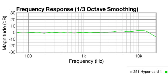
As you move one position clock-wise, what I called Hyper-Card 1, you see the mid-range lift a little.
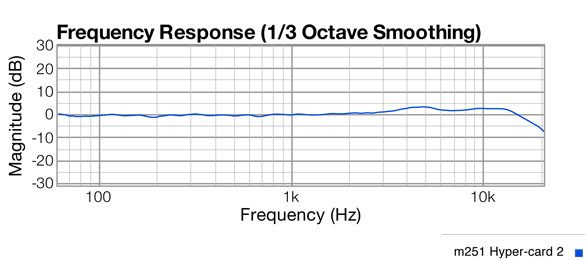
For Hyper-card 2, which is more like a standard hyper-cardiod pattern, a little more mid range lift. In fact this pattern looks very much like the published response of the Neumann u47!
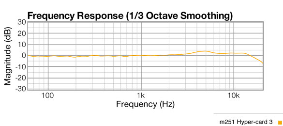
Now Hyper-card 3 begins to bring down the top end a little.
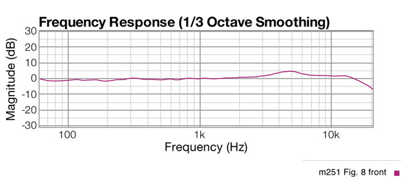
And the Figure 8 pattern takes the top end down the most and the mid-range lift comes up a full 5dB.
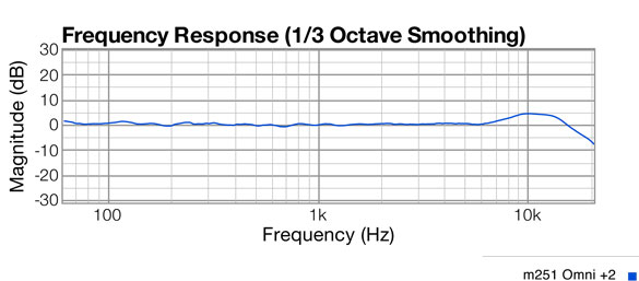
The Omni Patterns
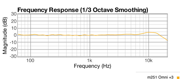
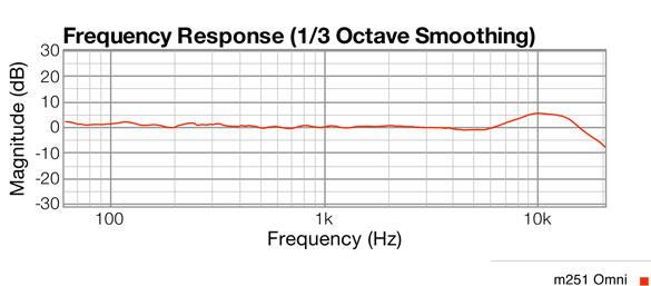
Below we see the full omni pattern raises the high end at 10K, pushes down the upper mids and lifts the bass a little.
Omni +1 click clock-wise flattens out the low end and upper mids.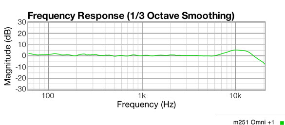
Omni +2 continues in that same direction
And as we return the control to near centre, Omni +3 is almost the same as Cardiod but with a little more top and a little less mid lift.