Making An 800 Clone, Pg2
Brian Fox, May 28, 2016
Large Output Transformer
Large ferrous cores are the only way to make a transformer operate at extended low frequencies and at high output levels at the same time. Transformers operate on the magnetic field created by the input signal and if the field exceeds what can be held in the magnetic core material the transformer’s output drops. This is a good decision by *Sony and was also used in the U47 and the original c12 design. Big iron is good.
K67 Style Capsule
Using a K67 capsule is not special. The K67 design has been copied by numerous microphone manufacturers. The K67 is simpler to make than the K47 and because it is two separate capsules for front and back, you can select pairs of capsules that match perfectly to create the final two-sided capsule. The Sony design is not an exact replica and shows a response that has less mid-range lift than a typical K67. The high-end lift is about the same amount as a K67. This is the single most important part in setting the tone of the c800 in our opinion.
U47 Input Connection
The c800 does something that I know makes a difference in the sound of a microphone. When you connect a cardioid capsule directly to the tube control grid (input) you increase the level hitting the tube versus an omni or multi-pattern input circuit. In my research this seems to give the microphone an edgier sound. Since tubes generate more second harmonic distortion as you drive them harder this makes sense. This is how Neumann wired the u47.
Fortunately if we try to build a c800 clone, this one is simple to duplicate.
The c800 Circuit
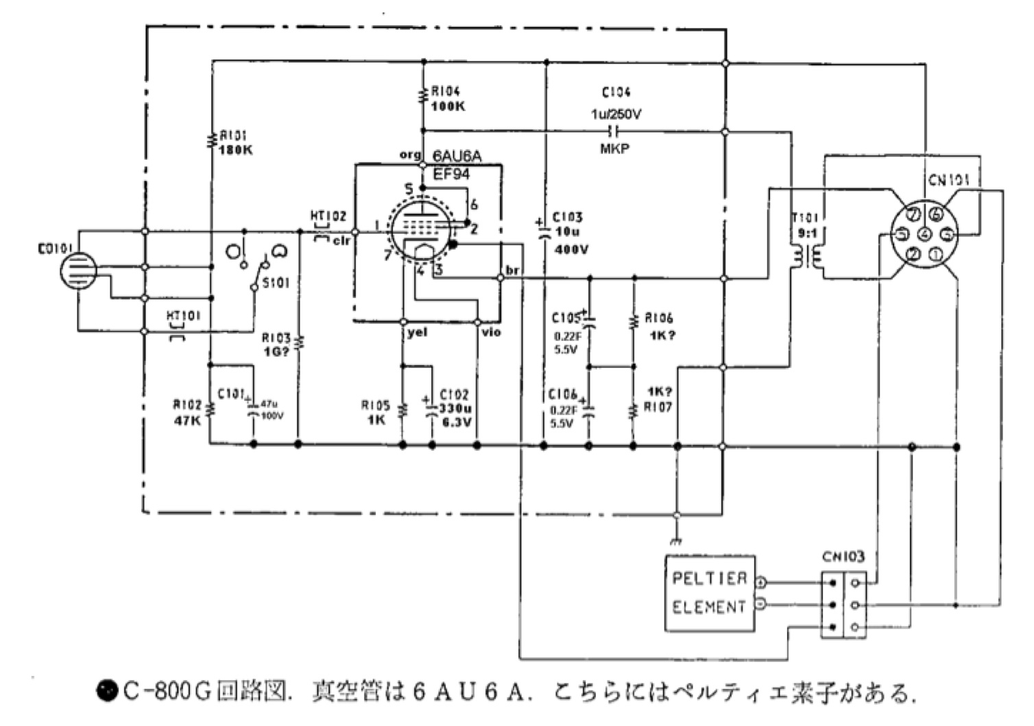
A few things become obvious when we look at the c800 circuit. It uses the ordinary Cathode bias, sometimes called auto-bias circuit created by R105 and C102. This is normal and very much less exotic than the Neumann circuits which used a fixed bias voltage. However with that large 330uF capacitor bypassing R105 the response will be flat down to very low frequencies. My one improvement would be to bypass c102 with a good film capacitor to be sure the response is also good a high frequencies. This is less of a problem with modern electrolytic capacitors, but a 330uF actually has a lot of internal coils that can be an inductive (acts like coil) impedance at high frequencies. So we would include a film cap just to be sure.
High Current Voltage Divider
When we take a look at the polarization voltage I see something peculiar. The capsule voltage is created by the divider R101 and R102. That’s not unusual but they used very low value resistors so that the divider circuit is consuming almost as much current (over 1 mA) as the tube. That is completely unnecessary and a little bit crazy. A capsule voltage circuit does not need to provide current, just a static voltage. These resistors could be much bigger as long as the ratio was the same (470K and 120K for example) and it would work exactly the same but would not load the power supply so much. What’s also strange is using these low value resistors meant Sony designers had to chose to filter it with an enormous 47uF capacitor. Much better filtering can be created by using higher value resistors with a small 1uF capacitor and adding a high impedance filter consisting of a 51M ohm resistor and little .02 uF film cap. Using this method also means you can never shock the capsule because the charging time for such a high impedance filter is over two seconds! This is a much better solution to get slow power up and ultra clean voltage, than using 2 vacuum tubes in the power supply like the c800 uses and infinitely more reliable.
Model 800 polarization voltage circuit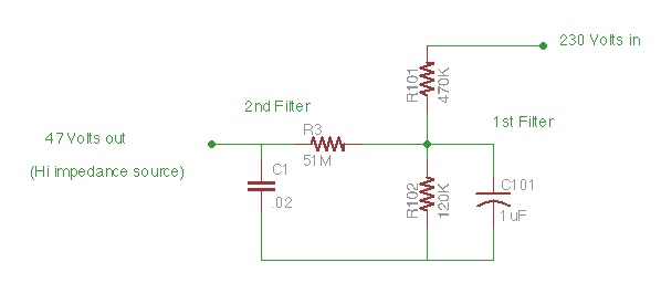
Power Supply Decoupling
Decoupling is a term that means removing the influence of something. In this case it is the influence of having a long wire from the power supply up to microphone. As the tube current varies with the signal this can cause the voltage to bounce up and down and degrade the quality of the output signal. The 10uF capacitor in the c800 (c103) stores up voltage inside the tube removing that bounce for all but the lowest frequencies. Another common way to get this disconnect from power supply variation is to use a resistor capacitor combination at the tube and this is what we did.
I did not have a 400V 10uF capacitor at the time, so I have more work to do to see if the 10uF capacitor really makes a big difference. I know it can't hurt.
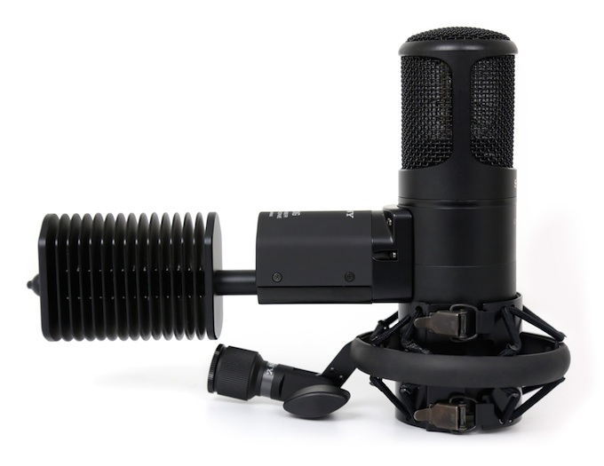
The FAR 800
So to quote Homer Simpson “I think I can handle this Marge”. In order to make a c800 sound-alike we started with the Nady 1050 microphone, which has a similar body size to the c800 and a similar head-basket size and cage density.
The other thing I like about the 1050 is that the tube socket is wired to the circuit board. This means we can rip off the existing wiring and re-wire it for any 9 pin tube we care to use.
Speaking of tubes, for this application I like the EF86. It is a great little small signal pentode tube that was designed to be the input section of high end audio gear. It’s available from a lot a suppliers and it has all the grids on a separate tube pin so we can triode wire it just like the 6AU6. It can handle the same current levels as the 6AU6 in triode mode, but it has a higher plate resistance however that does not create any sound compromise in my opinion, because it is not vastly different.
We used a fairly large high nickel alloy core transformer with an 8:1 ratio. This lets us make up a dB of signal versus a 9:1 ratio unit in the Sony. This transformer can easily output +4dBm of power with almost no distortion so that is no problem for mic levels.
We had to do some big modifications to the power supply to get the output to hold to 230 volts with the mic connected. The filter circuit is a 5 stage Pi network but the stock supply used some high value resistors so some of them had to be replaced. But this reduces the hum reduction in the circuit so we had to replace the filter caps with larger ones to keep the hum reduction the same value. We also removed the zener diode regulator and used an old-fashioned bleeder resistor.
The table below shows how we built our 800 “Sound alike”
Feature |
Sony c800 |
FAR 800 |
|
|
|
|
|
|
|
|
|
|
|
|
|
|
|
|
|
|
|
|
|
|
|
|
|
|
|
|
|
|
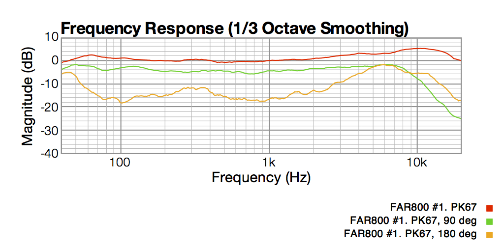
Our Response Graph
Note: Our graph starts at 40Hz and goes to 20KHz. We cannot measure below 40Hz.
Our PK67 capsule has 2dB mid range lift and crosses 0 dB at 20,000Hz. Our cardiod rejection measurement (180 deg) can never below 20dB because we are in not in an an-echoic chamber.
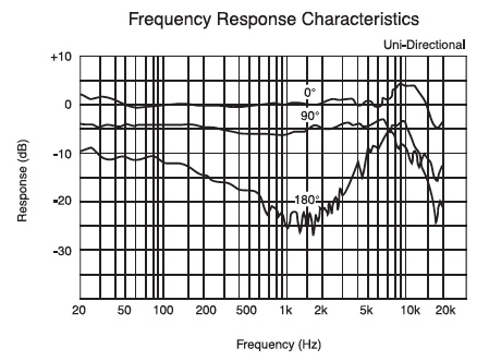
Their Reponse Graph
Note: Graph starts at 20Hz and goes to 25KHz
Sound Check
No EQ, No compression, recorded at 4", Cardiod
The Real Test
So all that writing to say, we see nothing particularly hard to duplicate in the c800 except that wild cooling device and there is no reason to have the Pelletier cooler if you choose a good low noise tube in the first place.
So our little EF86 is humming along at high voltage, biased to perfection and it has tons, and I mean tons of head-room with that nickel alloy output transformer.
The K67 capsule is pushing up the high end nicely and to my surprise the mic sounds like the bomb! I would not have believed it if I didn’t hear it. I tend to like microphones with a more neutral response yet this one, especially when worked close, in cardiod, has some kind of mojo going on that I could get used to.
There is one other thing that I know for sure. The FAR Model 800 will not have reliability problems because we did not choose a table-top radio tube for use in a studio microphone. That’s guaranteed.
If a microphone in the c800 style interests you send us a note to request a quote at: