How a Tube Amplifies
When I was a young student of electronics, I was doing most of my learning by bringing books home from the library (wow was that a long time ago) and hand wiring circuits. I remember an “ah ha” moment that happened when I suddenly realize how exactly a vacuum tube amplifier actually takes a tiny signal on the input and creates bigger signal on the output. I think it was shortly after I let a 300 volt DC power supply connect to my finger tips. When I regained consciousness... I said “AH HA” and a few other words too!
In this article I am going to share a way of understanding this that you probably won't find in an electronics text book. But for people who have no plans to design tube amplifiers it will give you a no-math needed mental image of how it works.
So before we jump into the tube itself we are going to start with a very simple circuit that uses resistors, called a voltage divider. You know it better as a volume control. So lets take a look at how a volume control works. I should add here that we are talking only about old fashioned analog circuits. A digital volume control works very differently.
A Volume control in analog circuits uses something called a variable resistor. A variable resistor, also called a “potentiometer”, has a ring of a resistive material, typically carbon and metal wiper than can rotate such that it can touch anywhere along the carbon ring.
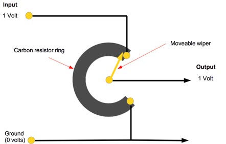
If we connect the top part of the resistor to an audio signal and connect the bottom to ground, we and can measure a signal from the wiper of the potentiometer. If the wiper is at the top of the ring the voltage will be the same on the input as on the output. If the wiper is at the bottom, it is connected to ground and so we get no signal.
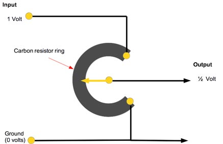
If we put the wiper in the exact middle of the carbon ring, we will see that the output is exactly half of the voltage at the input. Voila! We have divided the voltage by two.
Now to get us closer to our tube amplifier let's turn our volume control into two separate resistors, instead of a carbon ring.
Look at the schematic below. We have turned the ring into a resistor on top and a second equal resistance on the bottom.
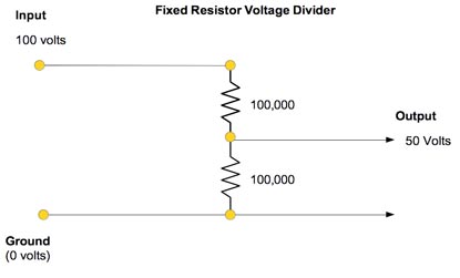
This voltage divider will do exactly what our volume control did with the wiper in the middle. Whatever voltage is at the top, will be exactly divided by two when measured at the junction of the two resistors.
So this is what happens when the resistors have equal “resistance” . Let's say each resistor has 100,000 ohms.Ohms are just a unit of resistance named after Mr. Ohm who discovered how the worked. You may have heard of Ohm's Law. That's the guy.
What do you think would happen if we changed the bottom resistor to 10,000 ohms?What will happen is the output voltage will be lower and that voltage will be proportional to the ratio of the two resistors. In this case it will be nine percent of the input voltage or about 9 volts. (If you are interested you can see the math for this here)
So we can see from this example that we can create a volume control, where we have one fixed resistor and vary the bottom resistor to get different output levels.
So What?
What has this to do with a vacuum tube amplifer you ask?
Well if we replace our bottom resistance with a vacuum tube, we can use the tube just like a variable resistor, only it has some magic properties. Read on squire...
Tube Refresher
First we need a quick refresher on how a vacuum tube works. A vacuum tube is called a “valve” in many parts of the English speaking world and actually it is a more descriptive name of what they really do. Whatever you choose to call them tubes or valves are named by the number of “electrodes” that are inside glass bottle. So a “Diode” has two electrodes and a “Triode” has three electrodes. The triode is the one we will concern ourselves with here because it is the simplest vacuum tube that can do amplification.
Look below at the different parts of the triode both in the illustration of how they are inside the a real tube and also make a mental note of how we will show them in the schematic view.
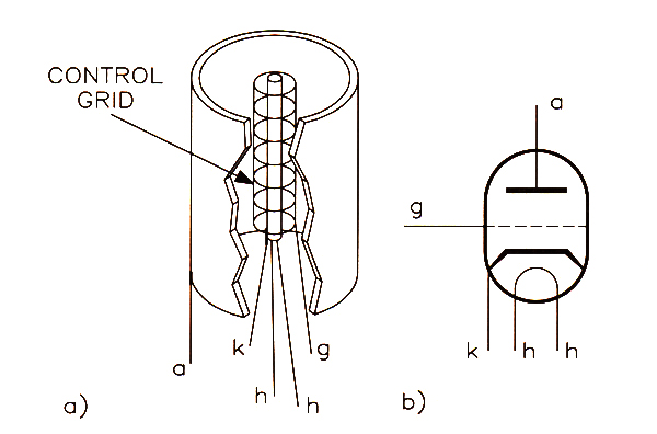
Key to the parts of the triode
a = Anode, K=cathode, g= control grid, h = heater
Here is what happens in the Triode:
-
The heater heats the cathode red hot (the little glowing thing you see inside the tube)
-
The HOT cathode creates a cloud of negatively charged electrons in the vacuum.
-
When a high positive charge is connected to the Anode, the electrons are attracted to it
-
This causes a current of electrons to flow from the cathode to the anode in the vacuum
-
The control grid is in the middle of the flowing current
-
A negative voltage on the control grid will repel the electrons, which are also negatively charged, back to the cathode.
-
If a high enough negative voltage is put on the control grid, the current can be made to almost completely stop (it really is a valve)
Although we call it a three electrode device there is reference to a fourth element called the “heater”. The “heater” is needed to get one of the parts, the cathode, hot enough that it can release a cloud of electrons into the vacuum contained by the glass envelope. In the very early vacuum tube designs the heater and cathode were one in the same thing because it was simply a light bulb filament! Modern tubes, separate the heater from the cathode to make the tube more efficient and reduce noise. |
By the way old tube techs still refer to the Anode as the "PLATE" because in the earliest vacuum tubes it was literally a little plate of metal stuck inside a light bulb!
My old tube transmitters had buttons on them that just said "PLATE". You were expected to know that the button would apply the high voltage to the Plate circuit.
So from the explanation you can see how a vacuum tube really is a “valve” for electricity. Now because it is continuously variable, we can also look at the tube like a kind of variable resistor. So that means we could replace the bottom resistor of our voltage divider example with a “valve”!
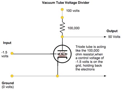
Now what do we have? We have our voltage divider like before, but it can be adjusted by putting a controlling voltage on the “control” grid of our vacuum tube. In the schematic you see that we have applied 100 volts to the top resistor. If we ground the control voltage so it has zero volts of charge, all the electrons will flow to the Anode. The tube will conduct electricity at it's maximum so this would mean the tube looks like a low value resistor. If we applied a negative control voltage to the control grid we reduce the quantity of electrons flowing in the tube and this equivalent to having higher resistance in our voltage divider. For our illustration we are showing our imaginary tube with -1.5 volts on the grid and this makes it behave like a 100,000 ohm resistor. So we still have 50 volts at the output of our voltage divider.
Magic Happens Here
Here is where the magic of amplification happens. A typical triode like a 12AT7 (ECC81) will go from that low internal resistance to very high internal resistance with only a small change of voltage on the control grid.
Typically a single digit number of volts on the control grid is all it takes. But if we measure the voltage changes at the connection of the Anode resistor and the Anode of the tube, the changes will be tens of volts!
Small change in makes a big change out
For example if we raised the Grid voltage from -1.5 to 0 volts the tubes effective resistance would drop to it's minimum, lets call it 10,000 ohms. This results in an output voltage of about 9 volts as we described before.
And if we lowered the control voltage down to -3 volts, holding back more electrons, the tube could behave like a 900,000 ohm resistor and we would see over 90 volts at the output. (use the link to the calculator to see for yourself)
So that 3 volt input change would make a 90 - 9 = 81 volt change on the output of our imaginary tube circuit.
The amount of difference between the input voltage change and the output voltage change is called the “amplification factor” and it varies by tube type. Amplication factor is how many times greater the output voltage is than the input voltage. So with the addition of a vacuum tube our little voltage divider becomes a voltage Multiplier! That's amplification.
Each tube type has it's own amplification factor that is the result of how the inside elements are mechanically arranged inside the tube. This is one of the reasons designers might choose one tube over another. For example the 12AX7 (ECC83) has an amplification factor of 100. If you want lots of gain, this is the tube to choose.
Problems in Paradise
So have you seen the limitations of our little circuit? One is not so obvious but here it is. The triode works great with the grid negatively charged compared to the cathode, in the repelling mode. It does not like to have the control grid go positive, meaning above zero volts. Why? Because as soon as the grid goes positive it begins attracting electrons like the anode. So the "internal resistance" we described will not behave normally, meaning an increase in the control voltage will no longer reduce the internal resistance of the tube the same way. Therefore our output voltage will not track with the input voltage. So we say the output is distorted compared to the input.
Likewise if we drive the control grid to far negative we will get to a place where the tube is cut off, meaning no current can flow through it. That means again that we are not changing the internal resistance of the tube with a change in control voltage because we have nothing left to control. This also means distortion. Our output is not tracking the input. So we have to keep the input signal in that linear "sweet spot" of tube's range if we don't want distortion.
Tube Bias
So how do we make sure the tube is operating in this sweet spot? Bias voltage is the answer.
To get our amplifier circuit to work properly we need to set the tube so that with NO signal, it is operating in the middle of that sweet spot range mid-way between zero volts and some negative voltage that is the cut-off point. That also means that our output is sitting close to mid-way between the 100 volts and 0 volts as well. We do this by applying a slight negative voltage to the control grid.
This little voltage is called the bias voltage and can be created by any method that makes the control grid more negatively charged than the cathode. We will not go into all the ways that can be done, but it can be as simple as a dry cell battery. In fact the earliest tube radios in the early 1920s used a dry cell battery just for the purpose of setting the bias voltage.
Here is how it would look if we built a little AC input amplifier. This circuit is called a "Plate Follower" because the output signal "follows" the voltage on the plate.
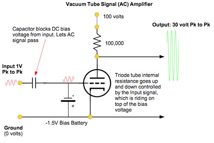 So now our 1V AC input signal is riding "on top" of negative 1.5 volts. With the signal being 1V peak to peak this means it is +0.5V and -0.5V, so this means our input, from the tube's point of view, will never be higher than -1V and never lower than -2V. So the bias voltage will keep the input signal from *ever going into positive voltage territory.
*Unless you overdrive the input of course. Now you understand why overdriving makes guitar amplifiers distort
Class 'A' You Say?
By the way, designing an amplifier to operate in this non-distortion, what we call linear mode, is what electrical engineers call “Class A” operation. It means the tube is always conducting electricity during normal operation. That's all it means. So don't get too excited when marketers brag about their equipment being “Class A”.
Single device Audio circuits that are not “Class A” are used in distortion pedals!
Class A/B, Class B amplifiers are biased closer to cut-off and used in push-pull output circuits like those in your guitar and bass amps.Class C amplifiers are biased hard cut-off and were/are used in RF Transmitter output stages that want high efficiency*Class D amplifiers run their devices in "switchmode" like a digital device. (ON or OFF) I have never heard of one built with tubes, but I suppose it could be done. The switching devices (MOSFETs) are used to make pulse-width modulation to literally control the output of a power supply and create audio signals. They are over 90% efficient. |
*I was told on Gearslutz that my Class A description was mis-leading and my Class D definition was wrong. I would not say that, but I have re-written them anyway to be more accurate. When I asked for something better, I did not get an answer...
Phase Reversal
Now some of you may have figured this out already, but one of the characteristics of the plate follower amplifier circuit is that when grid voltage goes up, the resistance of the tube goes down, which pulls the output voltage lower. This means the output is moving in the opposite direction of the input. We can say that the output is 180 degrees out of phase of with the input.
This is not too important as long as we recognize it. There are a number of ways to reverse the phase. Like running the signal through a second “plate follower” and reverse it again or put the signal into a transformer and reverse the output leads of the transformer. Anyway, I wouldn't have been thorough if I didn't mention this property of the plate follower amplifier.
Summary
So we hope you had your “ah ah” moment. Simply put, analogue vacuum tube amplification is using a small amount of electric charge to control a much bigger amount of electricity that travels through the vacuum in a tube. The big electricity must track the changes in the input as closely as possible for low distortion. Is it perfect? Never, but that's why we have so many different boxes to choose from in audio gear. It's the imperfections that give the unique character to our gear.
If you have any comments for us on this article send them to :
Content Disclaimer